Designed an AES Accelerator on FPGA for CPRE 4880 Embedded Systems Design.
Background
Advanced Encryption Standard (AES) is a symmetric encryption algorithm. AES is also more of a group; there is AES-128, AES-192, and AES-256 —where the number refers to the size of the blocks in bits. There are different ways AES can be used to provide security, but the most primitive usage of AES is AES-ECB (electronic codebook) where blocks of input are encrypted or decrypted independently with a key. AES-ECB can be used to implement more fancy usages of AES like AES-GTR and AES-CTR.
AES blocks are typically viewed from the “column-major” perspective. This means that, for example, we view the second byte of the block to be at the 1st column and 2nd row.
| b0 | b4 | b8 | b12 |
|---|---|---|---|
| b1 | b5 | b9 | b13 |
| b2 | b6 | b10 | b14 |
| b3 | b7 | b11 | b15 |
Finite Field $GF(2^8)$
Within the context of AES, math is done over the finite Galois Field $GF(2^8)$ Without going into too much detail, when we say add or multiply in the context of AES, we don’t mean the typical adding and multiplying, but instead how adding and multiplying is defined within the finite field. For example, an addition in this finite field, $a+b$, can be done via $a \oplus b$ (which is convenient for us from a hardware implementation perspective).
Algorithm
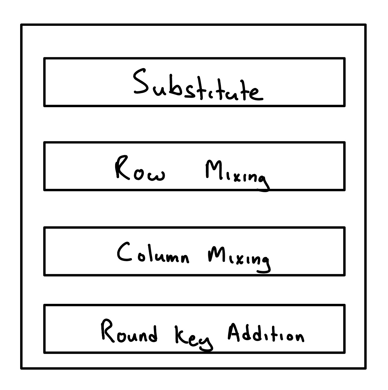
AES-128 has ten rounds. A single block of input, after being added with the key, needs to propagate through these ten rounds to get to the output. Each round (except the last —lacking column mixing) contains four major steps: substitution, row mixing, column mixing, addition.
A Single Round
Substitution
Bytes are substituted with other bytes with a substitution table. The substitution table is a constant set of values that doesn’t change at runtime.
Row Mixing
Bytes within a row are shifted around. The first row in the block is unaffected while the other rows bytes are rearranged.
Column Mixing
Column mixing is done with matrix multiplying each column against a known constant matrix, producing its new column. This is done for any column, $c$. The final round skips Column Mixing.
$$
\begin{pmatrix}
b_{c,0} \
b_{c,1} \
b_{c,2} \
b_{c,3}
\end{pmatrix}
=\begin{pmatrix}
2 & 3 & 1 & 1 \
1 & 2 & 3 & 1 \
1 & 1 & 2 & 3 \
3 & 1 & 1 & 2
\end{pmatrix}
\begin{pmatrix}
b_{c,0} \
b_{c,1} \
b_{c,2} \
b_{c,3}
\end{pmatrix}
$$
Column Mixing Matrix Multiplication
Round Key Addition
The related round key to the round is added with to the block producing the output block for the round. Each round gets a round key from Key Expansion.
Key Expansion
The round key that is added in the final step of each round is produced from the Key Expansion. The Key Expansion takes in the key block and produces 10 more keys for each of the rounds. Key Expansion involves its own algorithm to produce these derived keys.
Software Implementation
AES-128 ECB Encryption has been implemented in C from scratch. This proved useful for debugging and testing my hardware, as well as understanding the algorithm better. Once this was verified, it was used to make test cases for the hardware.
Hardware Implementation
With hardware, we have a few considerations to make: resources, max frequency, latency, etc. Our AES core pipelines each round, allowing continuous data to enter and exit while fully utilizing the rounds.
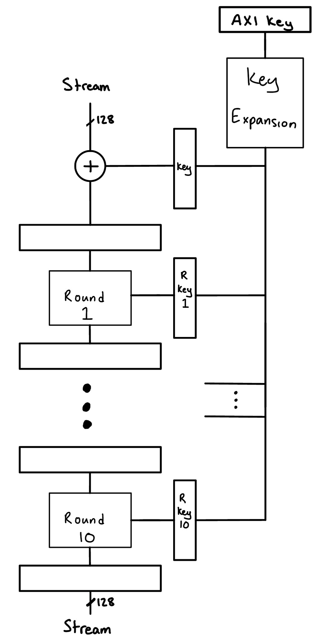
AES Top Level Hardware Design
The Key Expansion is also pipelined as well. We stream data in and stream data out via AXI Streams. We use a data width of 128 bits so we can take in a full block at a time. This is similar for the output stream. Our AES core acts as a AXI peripheral where the key can be changed via memory mapped registers. We represent the key with the “AXI Key” register being shown above the Key Expansion block. It should be noted though that this is actually an abstraction and that there are actually four memory mapped registers storing the totality of the AES key. It follows that changes to the key are not atomic, and this is taken care of in our state management and finite state machines.
Key Synchronization
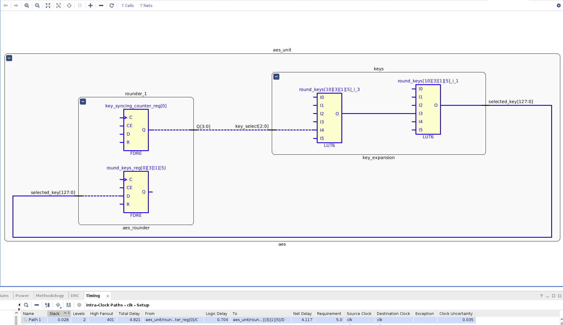
The Key Expansion unit houses its own registers storing the round keys it has computed as well as have a read port to read from those registers. We utilize a memory read port to reduce congestion in the FPGA, as opposed to just have eleven massive busses flying out of the Key Expansion unit. Each round has its own local round key register. As the pipeline fills up, the local round key registers can be filled up from the Key Expansion read port. This necessitates that the Key Expansion key derivation process is at least slightly ahead when the round units keys are being refreshed. The Key Expansion key derivation process and the local round key refresh sequence is on a as-needed basis (we don’t refresh or generate round keys when the AXI key hasn’t been written to). One of the benefits of having local round keys is that the Key Expansion can start working on generating new round keys for a new key while the current encryption transaction goes on in preparation of a new transaction.
We can derive the new round key from the last round key and a round constant that corresponds with the iteration of the round key we are on.
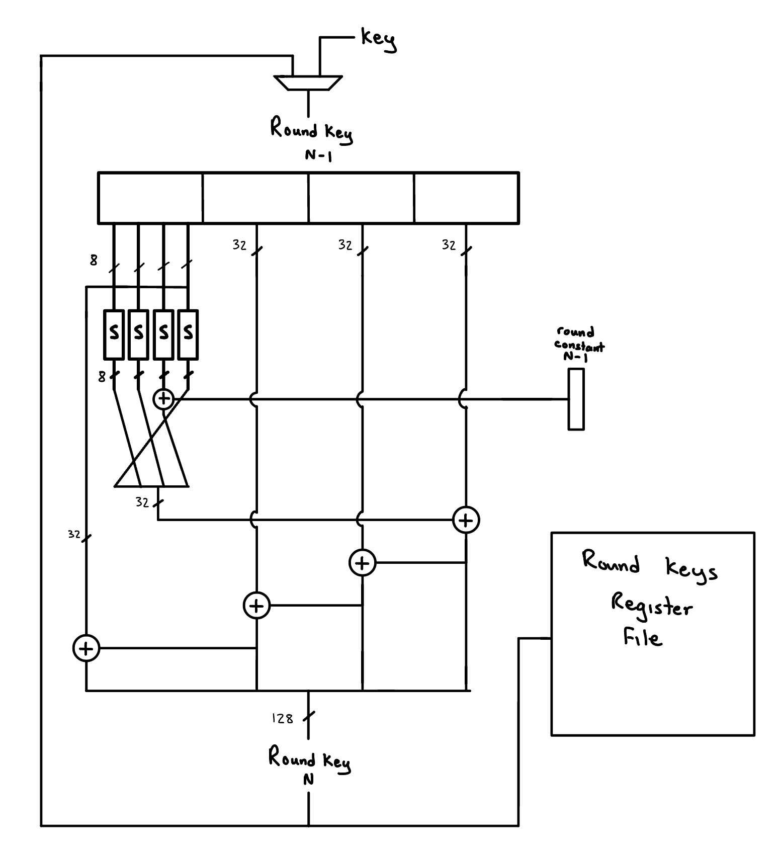
AES Hardware Next Round Key Derivation
Round
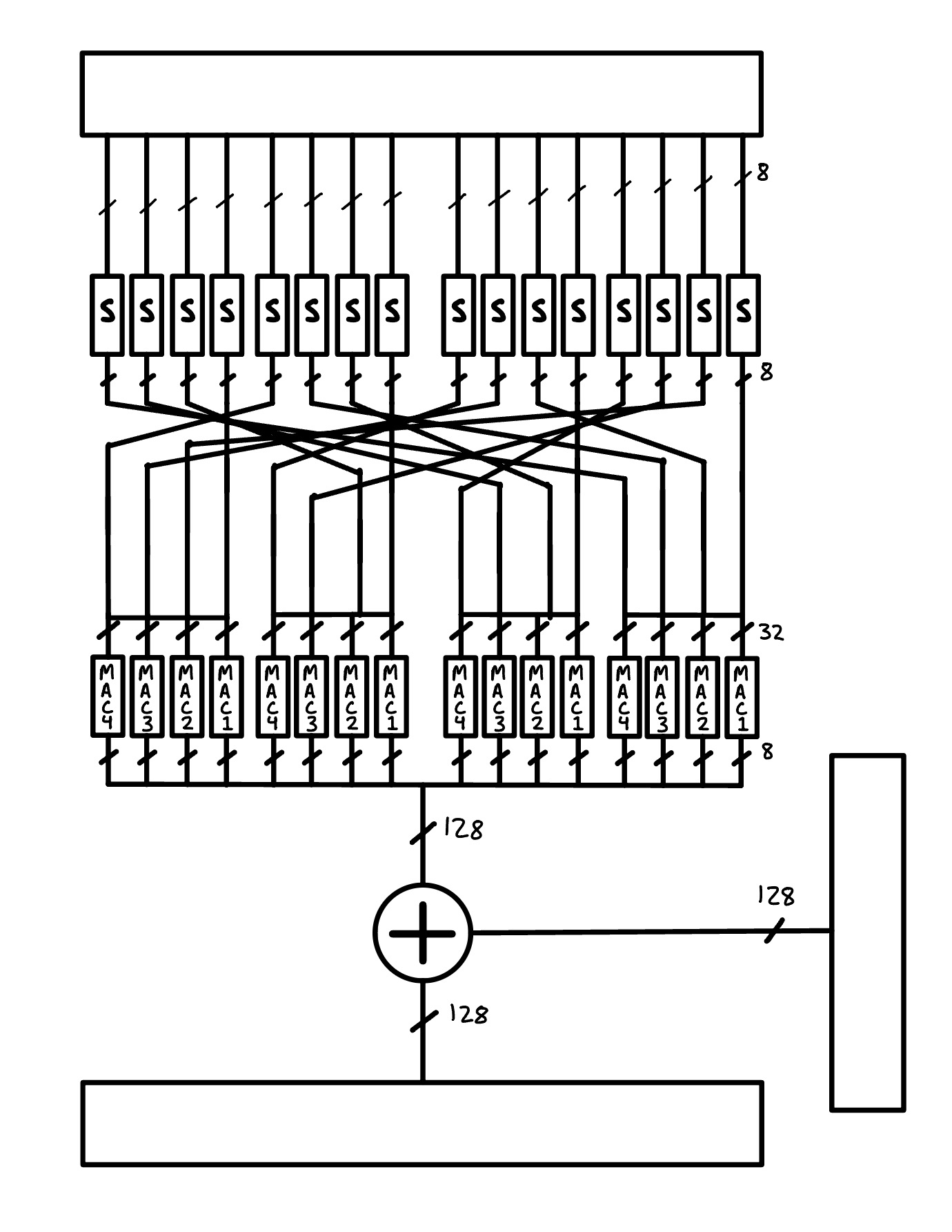
AES Hardware Round
Each round unit is sandwiched between pipeline registers. The S boxes refer to substitution look up tables. After the substitutions, the bytes are rearranged, taking care of row mixing, to then be fed into multiply and accumulate (MAC) units. We have multiple instances of these so to do them all in parallel. The MACs are used to take care of column mixing. After this, the block is finally added to the round’s respective key.
State Management
Transaction Tracking
![]()
AES Transaction Tracking FSM
If we are not in a transaction, idle, and we see on the incoming stream we read from, the read stream, that there is valid data, then this marks that we are starting a transaction. Regardless of wether we can accept data on that cycle or stalling for whatever reason, we transition into the transaction state. This is so we can keep track of what the key means in respect to our transaction. So once a stream transaction starts, we consider the available key at that time for the transaction allowing key derivation and local key refreshing to work with each other appropriately.
We go out of the transaction state once we see that our final output block is being read.
Local Key Refreshing
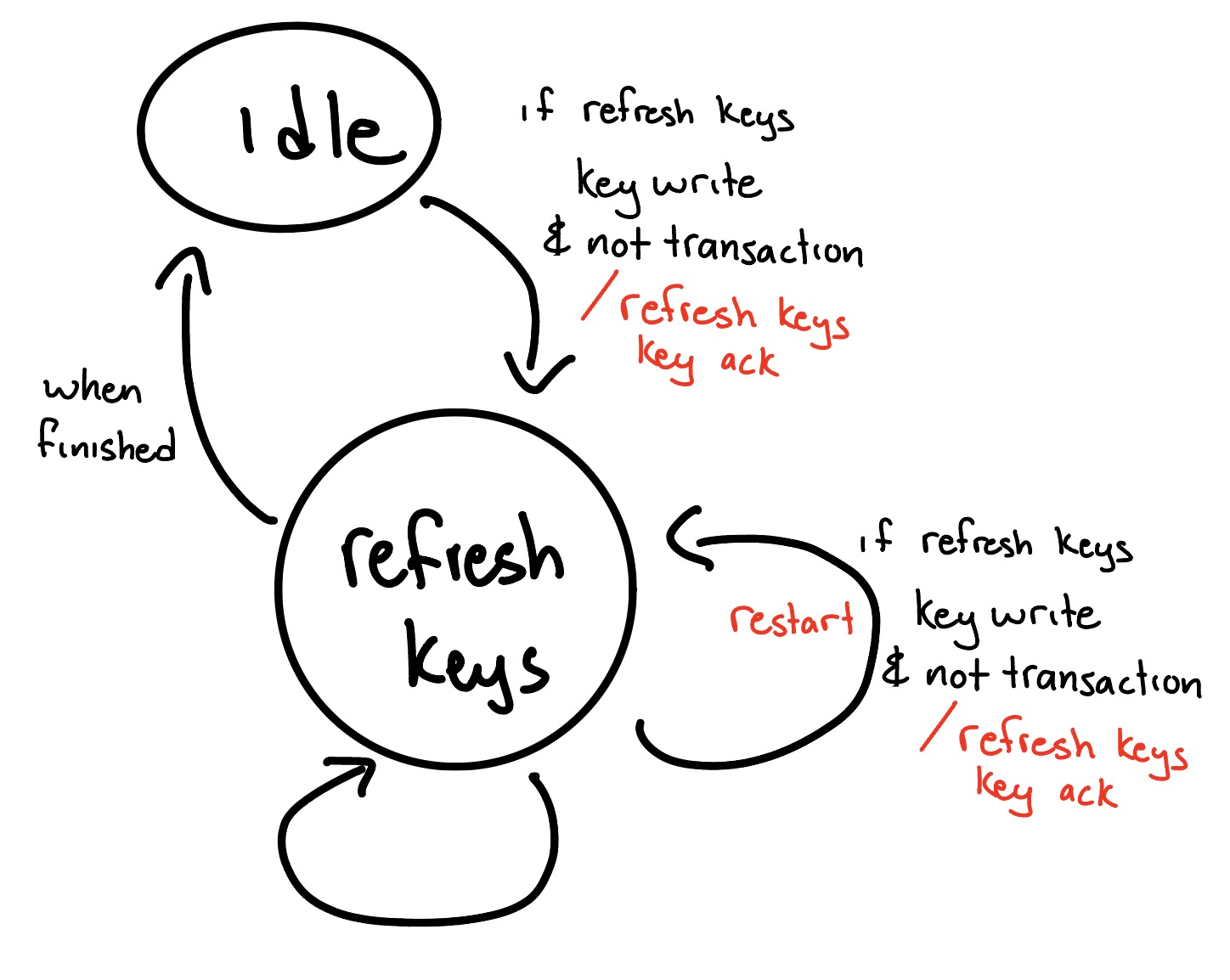
AES Local Key Refresh FSM
Key write is a pending signal relating to when the AXI key registers have been written to. Key write is asserted until it has been acknowledged. The refresh keys state updates the local round keys from the Key Expansion unit. If we haven’t been committed to a transaction and we have a pending key write that needs to be dealt with, we go into refresh keys state. Because the AXI key is made up of multiple registers, and so the key update isn’t atomic, we may have multiple sequential key writes. We account for this by being able to restart in the middle of a refresh keys process instead of being locked to a multi cycle process before getting to “try again”.
Round Key Derivation
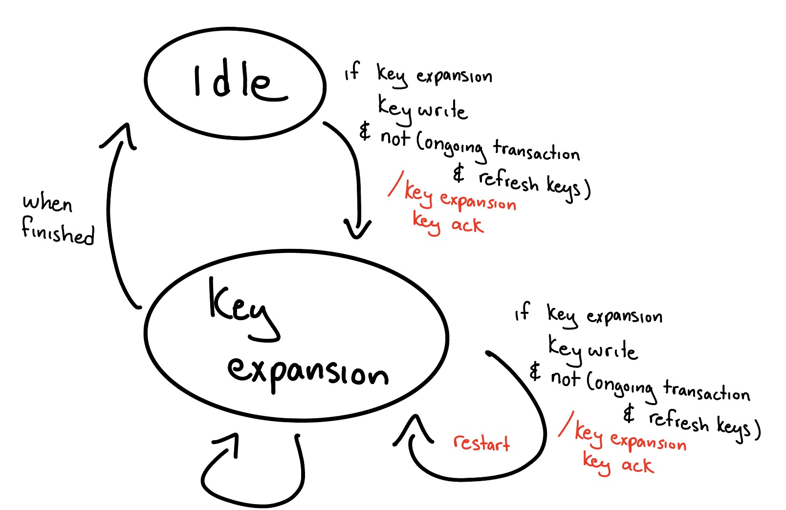
AES Key Expansion FSM
Similar to the Local Key Refreshing FSM, the Round Key Derivation FSM also has a pending key write signal that is asserted when the AXI key registers have been written to and de-asserts once acknowledged. If we have a pending key write, we go into the key expansion state as long as local key refreshing isn’t going on at the same time as a transaction. If key refreshing isn’t going on, but there is a transaction, it’s fine because the local keys have the old version so we can prepare for the new key and expand keys. If there is no transaction going on, then we can expand keys fine as there is no commitment. If key refreshing is happening during a transaction, we can’t start key expansion or restart it as the local keys are trying to sync up with Key Expansion unit. We are able to restart in the middle of the key derivation process for the same reasons mentioned in Key Refreshing FSM
Optimizations
The S boxes (Found Here
)
are each a look up table implemented with ROM intrinsics. This provided
better performance than just inferring the look up tables via something
like:
S_BOX[data].
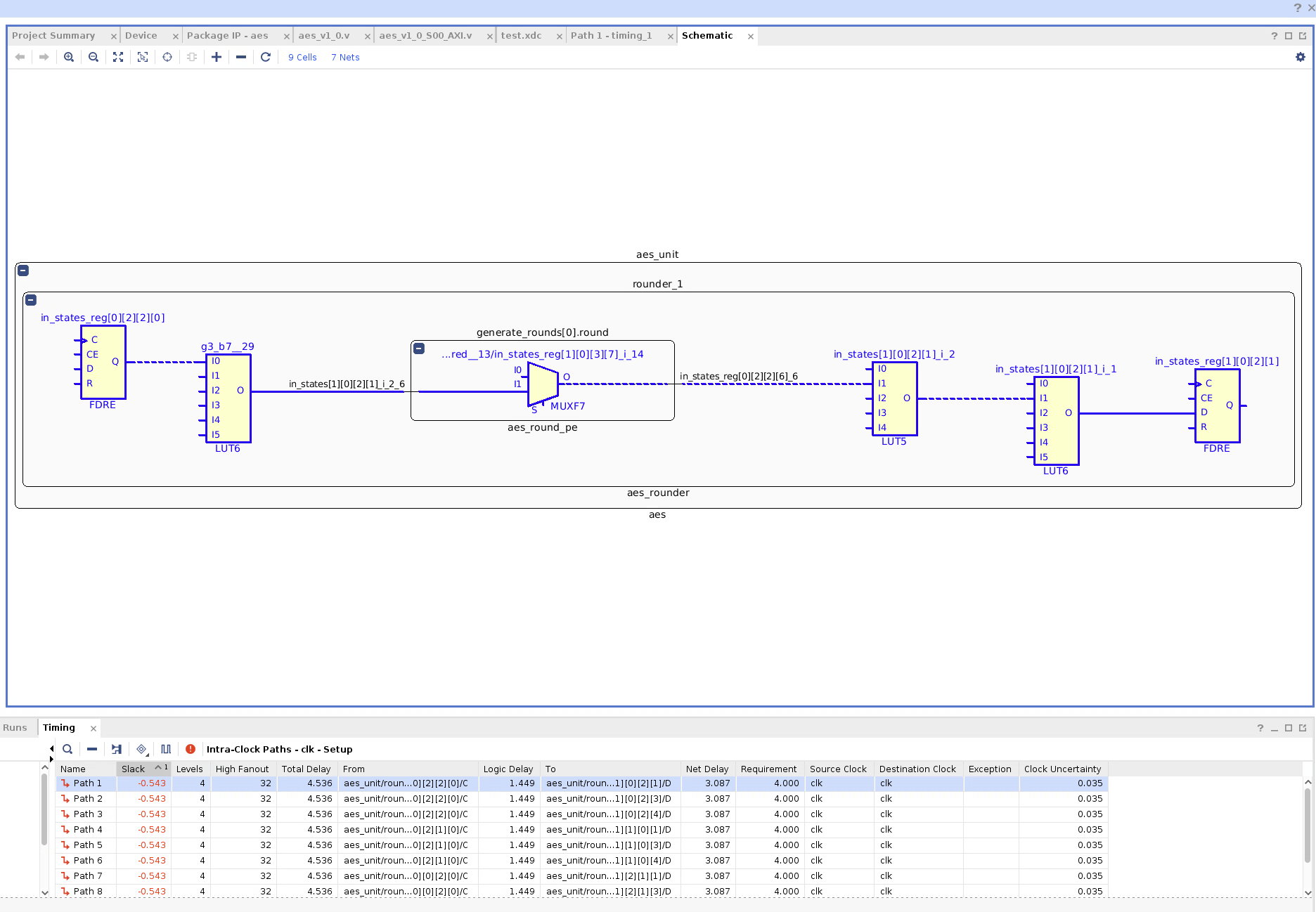
Synthesis Critical Path for AES Unit (Excluding AXI Peripheral) With Inferred S-Box Look Up Tables
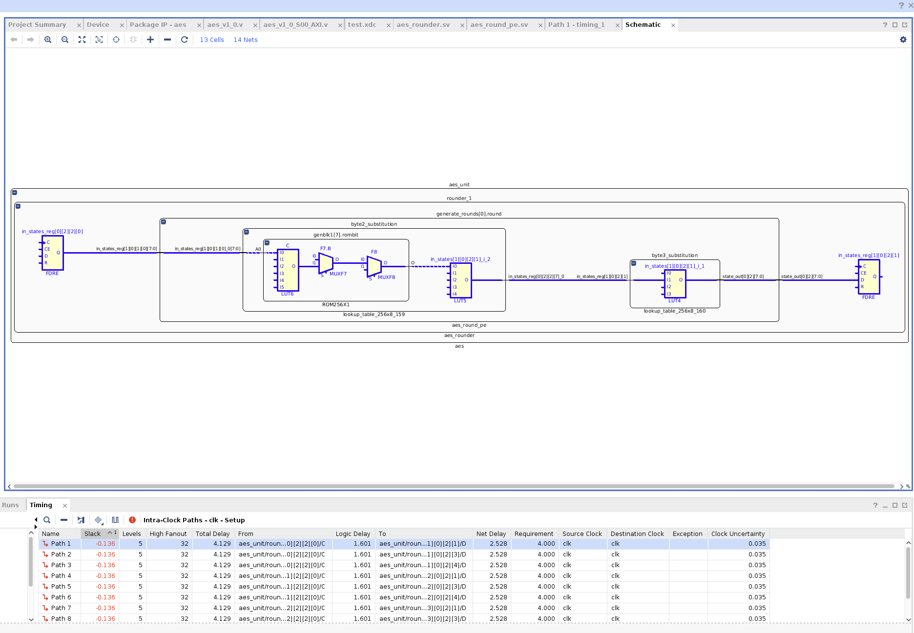
Synthesis Critical Path for AES Unit (Excluding AXI Peripheral) With S-Box via ROM Intrinsics
Using the ROM Intrinsics, the logic delay of the critical path is worse but the net delay is better such that the total delay is better. This isn’t Implementation though.
In Implementation, the key generation seemed to be critical path. With switching to to using ROM intrinsics for the S-Box look up table, slack seems to have reduced from around -0.9 ns to around -0.7 ns.
We changed to computing the round constant look up a cycle before it’s needed. Even though it can be done in parallel during the relevant cycle without extra logic delay, to have routing come out of a register seems preferable to having it come out of LUTs.
With lowering our goal frequency to 200 MHz and running Implementation, we see that the most critical path is the combinatorial read port of the Key Expansion unit:
Implementation Critical Path for AES Unit (Excluding AXI Peripheral)
Using a non combinatorial read port may require us to have an extra cycle where the key expansion has to be ahead of the rounder. Considering that the timing of this critical path is similar to that of the next most (unique) critical paths, fixing this with adding a potential extra cycle of latency while just having a different, but almost same delay, critical path doesn’t seem worth it.
Theoretical Performance
Assuming the pipeline is filled, the operating frequency is 200 MHz, and that we are streaming in a block and streaming out a block every cycle, then we have:
$$ 16 \frac{\textup{bytes}}{\textup{cycle}} \times 200 \frac{\textup{M cycles}}{\textup{second}} = 3.2 \textup{ GBps} $$
AES Hardware Core Testing
Using the Zedboard, the HP memory buses data widths are constricted to a maximum of 64 bits. This is an issue considering that our AES core takes in 128 bits at once. For our testing, we use two HP memory ports for the read and write channels of the DMA (with a 1 to 1 AXI interconnect in between). This is to reduce the memory bottleneck. The DMA critical path doesn’t support our frequency of 200 MHz so the frequency has been set to around 142 MHz.
We can test our hardware AES core against a AES software implementation found online. The software was compiled with -O3. Testing encryption on a around 14 MB video using both software and our hardware AES core:
| Timer Cycles | Time (seconds) | Bytes | Throughput (MBps) | Throughput (MBps) Including Cache Flushing and Invalidation | |
|---|---|---|---|---|---|
| Software | 939762981 | 2.819289 | 14162363 | 5.023 | |
| Hardware | 4132842 | 0.012399 | 14162363 | 1142.262 | 376.393 |
The hardware has over 200 times the throughput of the software implementation.
The 1.142 GBps is consistent with the 3.2 GBps theoretical throughput if you keep in mind the memory bandwidth is half our assumed theoretical memory bandwidth.